English
 Deutsch
 Espaniol


Correct measurement and examination in fiber optic wire installation are significant in establishing overall network performance and integrity. A crucial signal loss may cause unstable transmission. How to know the worth of losses upon the fiber connection? This article will guide you to figure out the failures and examine the fiber connection performance.
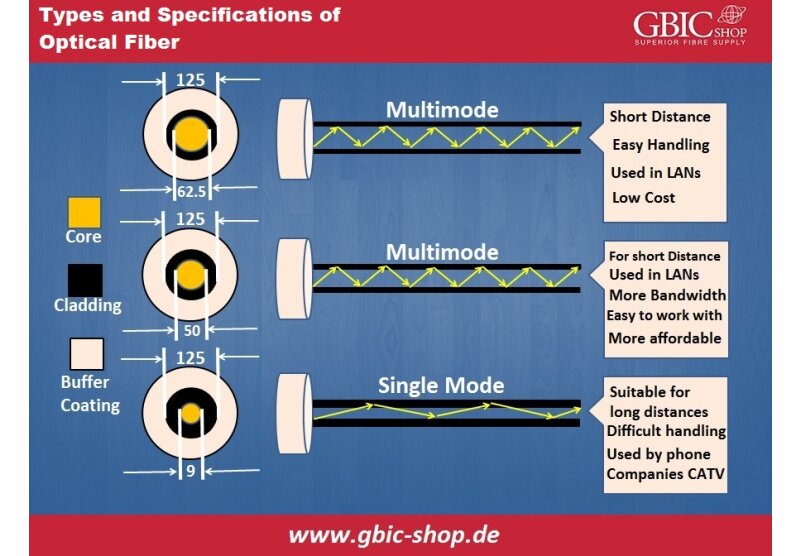
Types of Optical Fiber Losses:
How can we define fiber loss? Various factors cause light loss, like connector loss, bending, intrinsic element absorption, etc.
We can also call fiber loss attenuation loss or optical fiber attenuation, which counts light loss between output and input.

Fiber optic losses contain dispersion loss, scattering loss, and absorption loss. Structural defects generate them, and Extrinsic Fiber Optic Losses comprise bending loss, connector loss, and splicing loss. We can categorize fiber optic losses into extrinsic and intrinsic ones based on whether the cause of failure is operating conditions or inherent fiber optic characteristics.
Standards for Optical Fiber Loss:
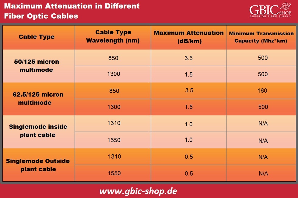
TIA (Telecoms Industry Association)/EIA (Electronics Industry Alliance) develops the standards TIA/EIA, which determine performance and communication requirements for optical fiber connectors, cables, etc. We widely accept and use them in the fiber optic industry. The highest attenuation is the coefficient regarding optical fiber cable, and we can express it in decibel/kilometer units. It is among the significant parameters for the measurement of fiber loss. According to EIA/TIA 568, we have shown the highest attenuation for various types of optical fiber cables in the graph below:
In What Way Can we Calculate Optical Fiber Losses?
To observe if the connection runs appropriately, we must perform the given calculation.
Calculating Fiber Optic Losses:
It is generally the situation to calculate the highest signal loss beyond a given optical fiber connection during the fiber optic cable installation. Firstly, you should know the fiber optic loss formula:
The Total Connection Loss = Splice Loss + Connector Loss + Cable Attenuation
Splice Loss (decibel) = Allowance of Splice Loss (dB) x Amount of Splices
Cable Attenuation (decibel) = Highest Attenuation Coefficient (decibel/kilometer) of Cable x Length (kilometer)
Connector Loss (decibel) = Allowance of Connector Loss (dB) x Amount of Connector Pairs
As the formulas indicate, the total loss is the highest amount of the poor variables in a fiber optic segment. We should note that this methods total failure calculation is only an assessment that presumes the available value of intrinsic losses. Therefore, there is a possibility of higher or less actual loss depending on different factors.
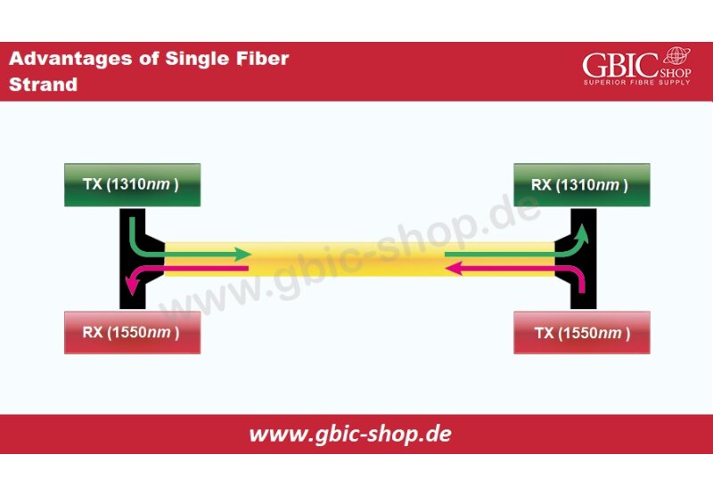
Let us have a practical example to signify the steps of calculation. There is the installation of an SMF cable between two places with a range of 10 kilometers 1310nm fiber optic wavelength. The cable possesses one splice and two pairs of a connector.
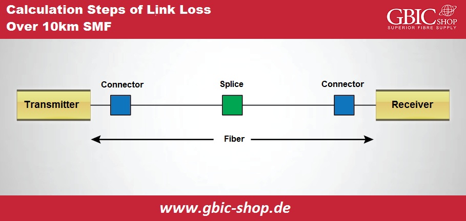
- Calculate attenuation loss of fiber cable. The graph above shows that 1310 nanometers light attenuation SM outer fiber optic cable is 0.5dB/km. So, the total attenuation of cable is 0.5dB/km x 10 kilometer = 5 decibels.
- Calculate the complete connector loss. The actual fiber connector loss within practical calculation stands for the value within the optical fiber cable specifications which the suppliers provide.
- Therefore, we have the total connector failure as 0.75 decibels x 2 = 1.5 decibels. Utilize the TIA/EIA highest loss of one pair as 0.75.
- Calculate the total splice failure. Utilize the TIA/EIA highest loss like 0.3 for one splice. So, the entire splice loss as 0.3 decibel x 1 = 0.3 decibel.
- Calculate the more component loss if we have any more components like attenuation.
- Add the splice loss, connector loss, cable loss, and total connection loss. The entire loss for this connection is 5 decibels + 1.5 decibel + 0.3 decibel = 6.8 decibels.
Note that we have just assumed the estimates. The most accurate and easiest method is to utilize an actual connections OTDR trace.
Calculation of Power Budget:
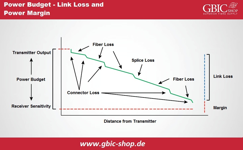
How does the value of this connection loss matter for the entire transmission? We will mention here another expression, "power budget" We use it to compare with the total calculated loss to confirm the cable plant installation is proper. The connection will function typically only if the connection loss is in the loss budget. We calculate the power budget (PB) because of the difference between the outputs transmitter within the fiber (PT) and the receivers sensitivity (PR). We have PB = PT - PR as the calculating formula. Suppose if the output power of an average transmitter is -15dBm, the receivers sensitivity is -28dBm. We will have power budget as -15 decibel – (-28 decibel) = 13 decibels.
Calculation of Power Margin:
After calculating the power budget and link loss, there is the possibility of calculating the power margin. We call it safety margin. It signifies the power amount attainable after subtracting connection loss from a power budget. We have the formula PM = PB - LL.
Take the case of 10 kilometers SMF as an instance, the connection loss is 6.8dB, and we have a power budget of 13dB. So, 13 decibel – 6.8 decibel = 6.2 decibel is the safety budget. A value higher than zero shows that the connection has enough power for communication.